Burrs ... Cross Hole Deburring
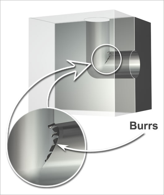
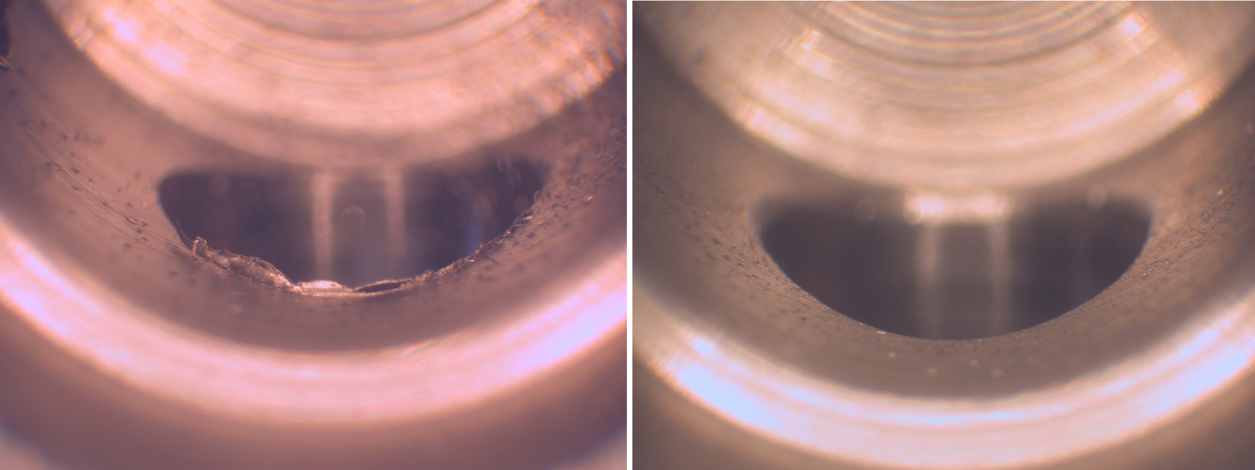
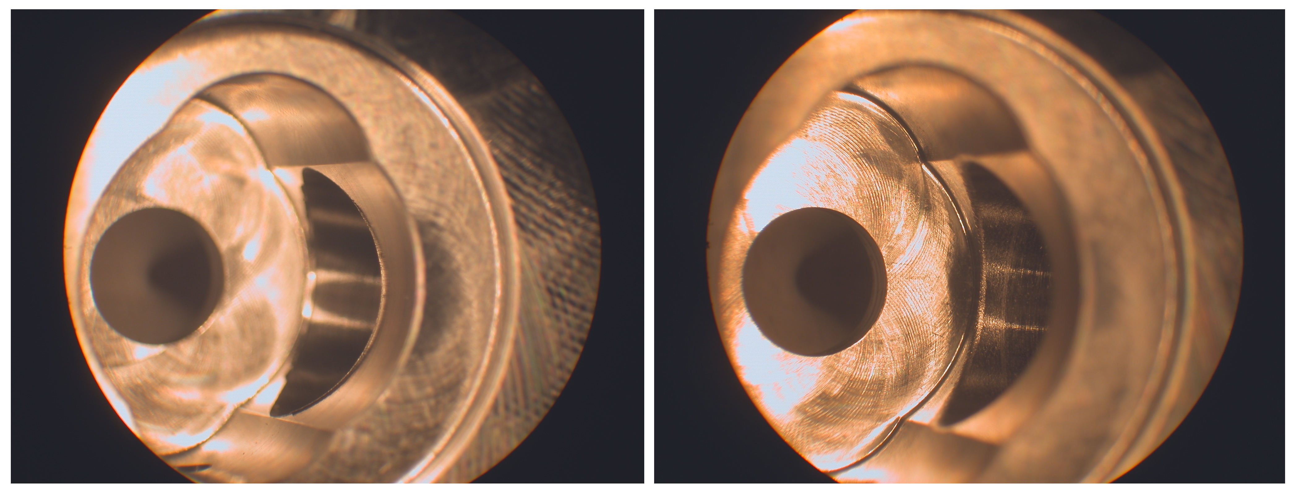
One of the most nagging problems in manufacturing is the deburring of cross-drilled holes. Burrs are always created where the crossholes exist. Getting at the burrs, let alone removing them, can be a real challenge.
A handful of methods are commonly employed for dealing with these burrs: sandblasting, extrude hone, and of course, manual deburring with knives, abrasive stones, brushes, burs, etc. While effective to varying degrees, these methods have their drawbacks. They're all off-line processes, i.e. they are a separate operation. Parts need to be handled and/or moved from machining to deburring. Often deburring is an out-sourced operation. The extra handling, movement, queue, transport, etc. represent non-value added operations. Sandblasting, extrude hone, and similar devices involve capital investment, often substantial, or again, outsourcing. Manual deburring, as everyone knows, is very labor intensive, as well as craft sensitive.
ORBITOOL for Cross Hole Deburring
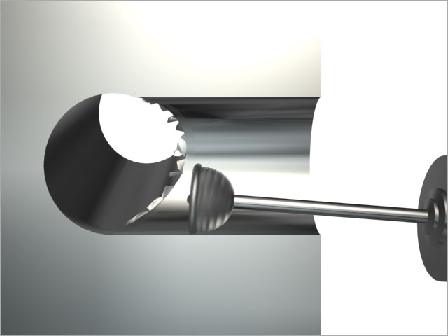
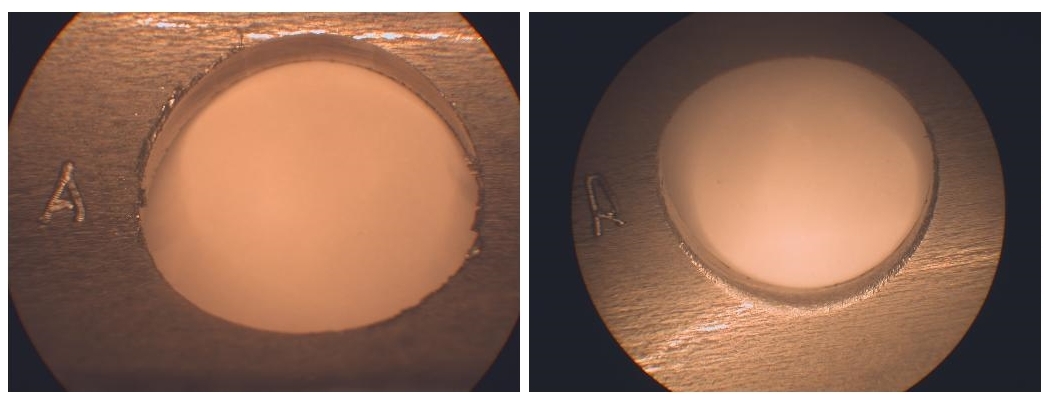
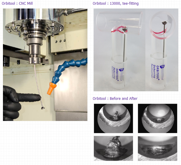
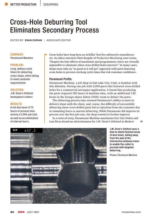
J.W. Done Corporation developed the ORBITOOL in response to this situation. It is the only deburring tool capable of in-process deburring of cross-drilled holes. The tool is used just like any cutting tool found on a lathe turret or tool magazine of a milling machine. It removes burrs specifically from the intersection of the crossholes. The operation can be tailored to leave a minimally broken edge or a blended radius.
Evaluating ORBITOOL with Manual Lathe
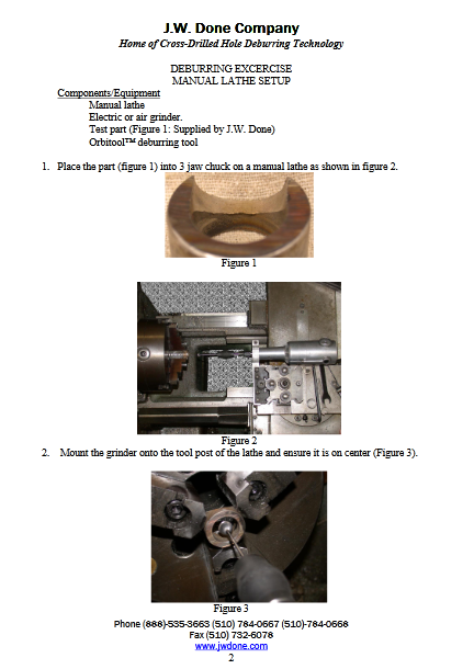
First-time users are strongly encouraged to go through a deburring exercise on a manual lathe in order
to 1) become familiar with how the tool operates, and 2) see first-hand what the tool can do.
We suggest a manual lathe for this exercise, preferably one not involved in production, as it makes
sense not to tie up a piece of production equipment when trying out a new process. Most shops have
a manual lathe sitting idle somewhere.
Setting up a manual lathe for using ORBITOOL use is straightforward and clearly illustrates the
principles of operation, i.e. the tool moves required, tool and part rotation, feeds and speeds,
and ORBITOOL motion during operation.
If you have not already done so, download the Deburring Exercise Guide from the INFORMATION &
DOWNLOADS page. The guide provides detailed instructions on how to deburr a sample part (provided by
J.W. Done Co.) on a manual lathe.
We are confident that you will be impressed with the tool and will want to introduce it into your
production. Contact us for help with specific process parameters. We can also provide a CNC
program macro to help get you up and running with ORBITOOL.
If however, after completing the exercise, you are not satisfied with the results, you can return
the tool to J.W. Done Co.
Videos
Photos

How to buy
Buy direct from J.W Done Co.
- Phone (888) 535-3663 or (510) 784-0667
- Fax (510) 732-6078
- E-Mail: info@jwdone.com
We also accept MASTERCARD, VISA, & AMERICAN EXPRESS.
Non-standard tools are quoted upon request.
Buy from your preferred tool supplier.
Have your preferred supplier contact us.
Customer Feedback
I just wanted to say thank you for making a cost effective tool that delivers it's promise on deburring cross holes with such simplicity yet effectiveness. It has reduced our deburr process on a Job Quantity of 2,000 parts from 120 hours to deburr manually by hand now down to 20 hours with consistent quality results. This tool should be a household name for any machine shop especially when dealing with deburring cross holes on small tight tolerance parts.
So thank you for a phenomenal product.
Bosch-Rexroth of Fountain Inn, South Carolina is a builder of hydraulic pumps for the off-road industry. It is extremely critical that the finished products maintain a high level of cleanliness for correct performance in the field.
Cross hole contamination has been a large problem with the production of these components. Because of this problem, the Engineering Department has been looking for a tool that would quickly and safety remove burrs from cross-hole drilled holes in castings produced, without damaging any entities between the cross hole area and outer casting surface.
Bosch-Rexroth of Fountain Inn, South Carolina has been using the Orbitool since late winter of 2007. Once our operators understood the proper use of the tool, they found the tool to be extremely effective on both housing and port block castings. In early winter of 2007, only (1) machine cell worked with and tested the tool. Today the tool is used in ten different areas and Bosch-Rexroth Engineers are seeing additional areas thee tools can and will be used in the near future.
We have a true success story with one of our customers. We had
for years sold them carbide burrs to deburr their parts. They
switched to the ORBITOOL and are so happy with the new tool they
went out and found us a customer to buy the rest of the carbide burrs
so that they wouldn't have to use them.
Now all we stock for this customer is ORBITOOL.
I have been using the J.W. Done deburring system for about two years now as a stand-alone system for deburring the intersections of titanium tees and elbows. These parts require a controlled radius at the intersections with no hand burring allowed. This process was previously accomplished using electrochemical deburring, which required extremely complicated tooling and the process was at times not under control. Since switching to the J.W. Done system we have a perfectly controlled process, no intricate tooling to manufacture, long tool life and very short setup times.
We are currently trying to implement this system into our everyday deburring system by either attaching the deburring equipment to our CNC's or building stand alone systems to run simultaneously with our machines.
CNC Mills and Lathes
CNC Mills
The fundamental motion of the tool is helical. The machine tool controller should be capable of helical interpolation, i.e. simultaneous 3-axis motion control. For mills without helical interpolation capability, a helix can be crudely approximated by combining circular interpolation with step-wise advancement of the tool in the Z-axis.
We offer a macro written in FANUC Macro B. This macro can be adapted to other controllers by knowledgeable programmers. Customized macros can be provided as well. Contact J.W. Done for details.
CNC Lathes
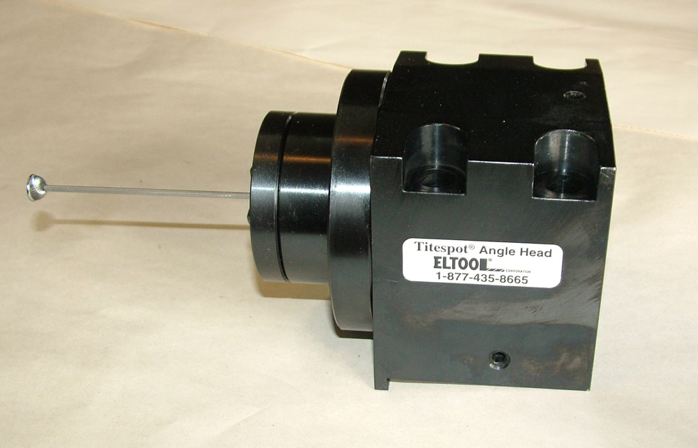
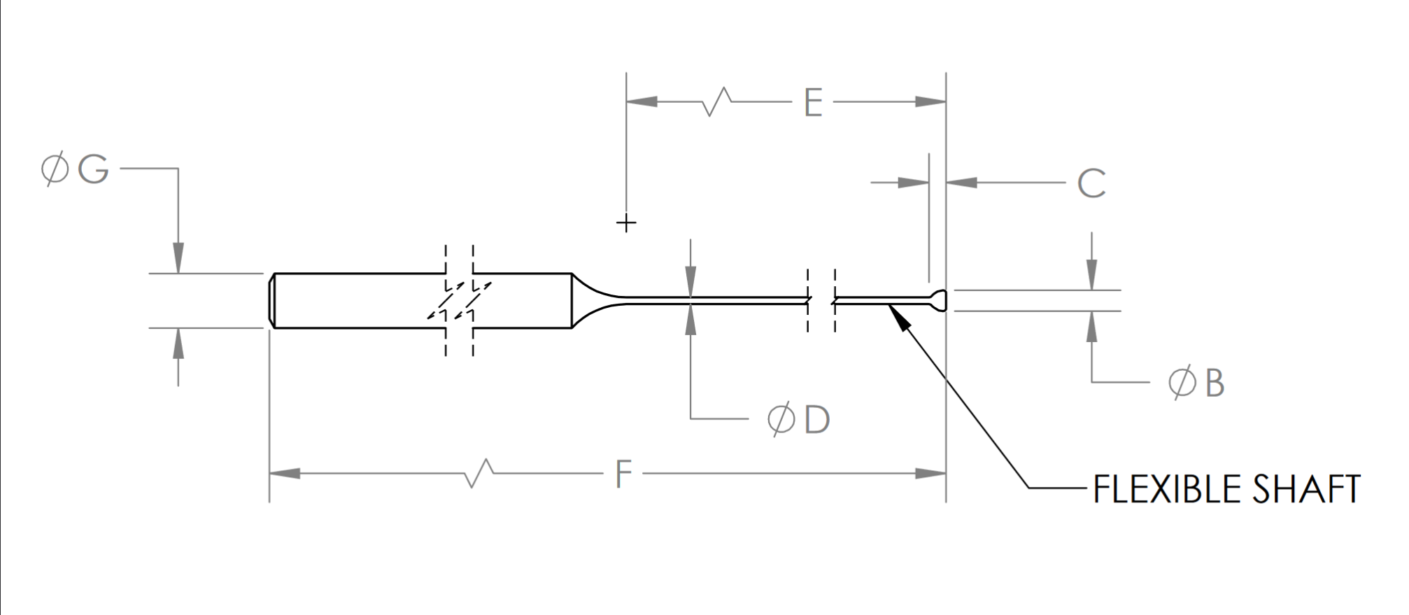
With lathes the helical motion is accomplished by offsetting the tool axis with respect to the axis of the hole, then advancing the tool in the Z-axis. Lathes with live tools are easiest to outfit with ORBITOOL deburring tools. Lathes without live tools can be fitted with moderately priced devices to run ORBITOOL deburring tools. The devices are either coolant- powered or driven by a motor and a flexible-shaft. Contact J.W. Done Co. for details.
Transfer Machines
Finally, after dreaming for two years about deburring at the spindle on machines that cannot interpolate, we have a solution - Orbidrive .
Please contact us for details.
Screw Machines
Finally, after dreaming for two years about deburring at the spindle on machines that cannot interpolate, we have a solution - Orbidrive .
Please contact us for details.
Manual Deburring
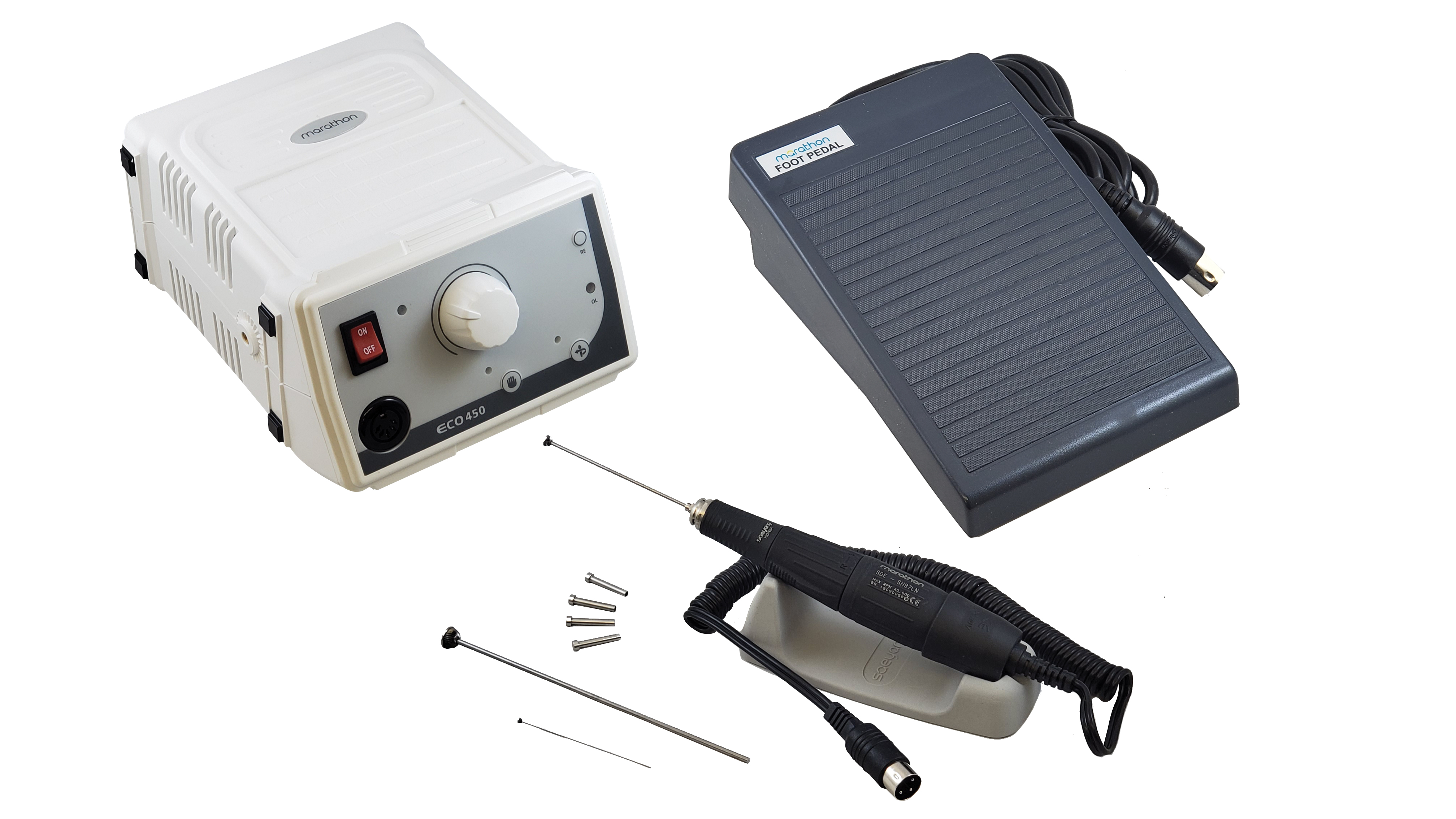
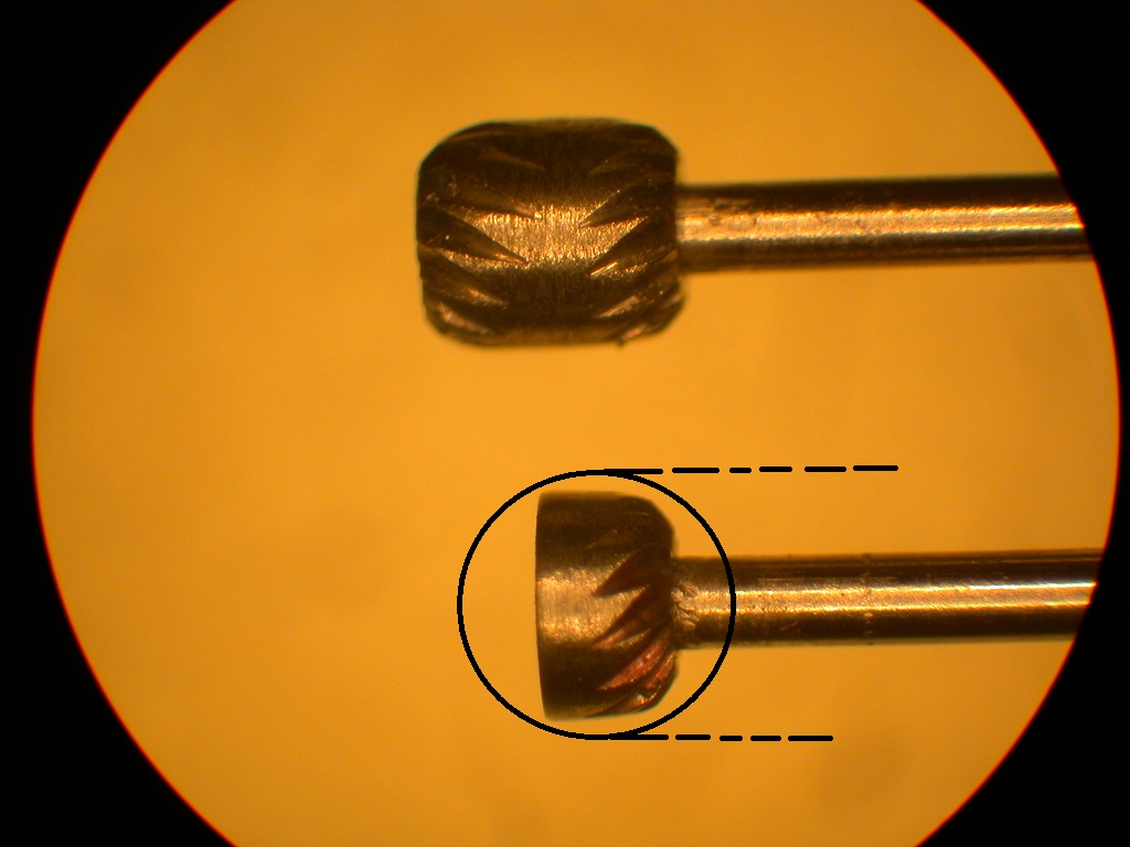
Manual deburring is readily accomplished with ORBITOOL deburring cutters mounted in electric hand grinders (air grinders are not recommended-the rpm's are too high). We offer the unit shown below, part number 30004.
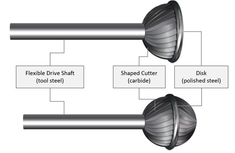
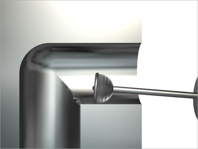
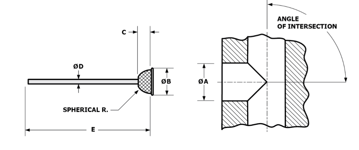
The patented design of ORBITOOL cutters provides a distinct advantage over conventional burrs. With ORBITOOL cutters it is much easier to control the deburring. Conventional burrs will remove material anywhere they touch the surface of the workpiece. Accidental/unintended contact damages the workpiece resulting in scrap or rework. With ORBITOOL cutters material removal occurs ONLY at the edge of a workpiece - where the burrs are! The disk on the end of the cutter prevents the tool's cutting edges from contacting the surface of the workpiece until the tool encounters an edge. Once the disk passes over the edge, the cutting edges can contact the workpiece and remove material. Moving the head of the tool back and forth over an edge is how you deburr with ORBITOOL cutters.
Because of its unique design, the results obtainable with ORBITOOL cutters will be superior to other hand deburring methods. As with other manual methods though, the results still depend on the skill and attention of the operator.
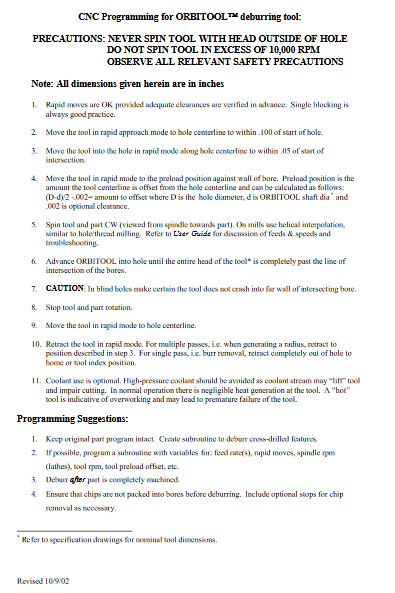
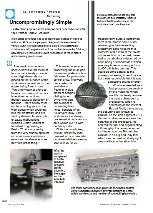
Safety is of paramount concern when deburring manually with any rotating cutting tool. Spinning any tool, especially one with a flexible shaft, in an uncontrolled fashion at high speeds is inherently dangerous. A fundamental feature of ORBITOOL cutters is the flexible shaft. This feature can be extremely hazardous when the cutter is used improperly.
With ORBITOOL cutters control of 3 factors is critical to safe operation: speed (tool rpm), shaft length, and contact or "engagement" with the workpiece.
SPEED: It is difficult to provide exact safe speeds for each size cutter as there are several variables involved. In general, smaller cutters can be used safely at higher rpm's than larger cutters. With ORBITOOL cutters use the lowest rpm that provides acceptable results. Charts indicating generally safe speeds for each size cutter are provided below. NOTE: the charts provide guidelines only-the user assumes all responsibility for determining the safe cutting speed (rpm) for a given situation.
SHAFT LENGTH: In general, shorter cutters can be used at higher rpm's than longer cutters. With ORBITOOL cutters it strongly advised the shaft of the cutter be trimmed as short as possible while still permitting the tool head to reach the edge to be deburred. NOTE: the user assumes all responsibility for determining the optimum safe length of cutter for a given situation.
CONTACT or WORKPIECE ENGAGEMENT: With ORBITOOL cutters it strongly advised that if the tool is spinning, the head of the cutter should be in contact with the workpiece. When deburring internal features though, it is generally sufficient that the head of the tool be fully inserted into the opening before the tool is spun.
FAILURE TO OBSERVE THESE PRECAUTIONS MAY RESULT IN CATASTROPHIC FAILURE OF THE ORBITOOL DEBURRING TOOL, RESULTING IN POSSIBLE INJURY TO THE OPERATOR AND BYSTANDERS, AS WELL AS DAMAGE TO THE WORKPIECE AND EQUIPMENT IN THE AREA.All other customary precautions associated with using cutting tools in powered hand tools must be observed as well. These precautions include, but are not limited to: use of guards, safety apparel (eye wear, face shields, hair nets, etc.), electrical safety, etc. SAFE AND PROPER USE OF ORBITOOL DEBURRING TOOLS IS THE RESPONSIBILITY OF THE USER.
The grinder kit shown above will include a set of shaft adaptor collets for the full ORBITOOL range. These collets may also be purchased separately for use in your own grinder. Available sizes below:
Reducing Sleeve (3.0mm or 1/8” O.D.)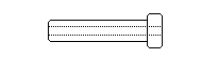 |
|
Contact J.W. Done
You can contact us by:Phone: (888) 535-3663 or 510-784-0667
E-mail: info@jwdone.com
Specifications and User Guides
 |
User Guide ( Updated 2024 ) |
 |
ORBITOOL Brochure |
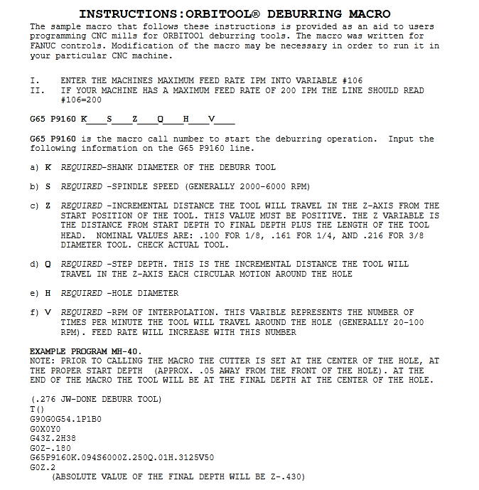 |
Programming Macro (FANUC) |
 |
Programming Guide |
 |
Deburring Exercise Guide |
 |
Part Photos |
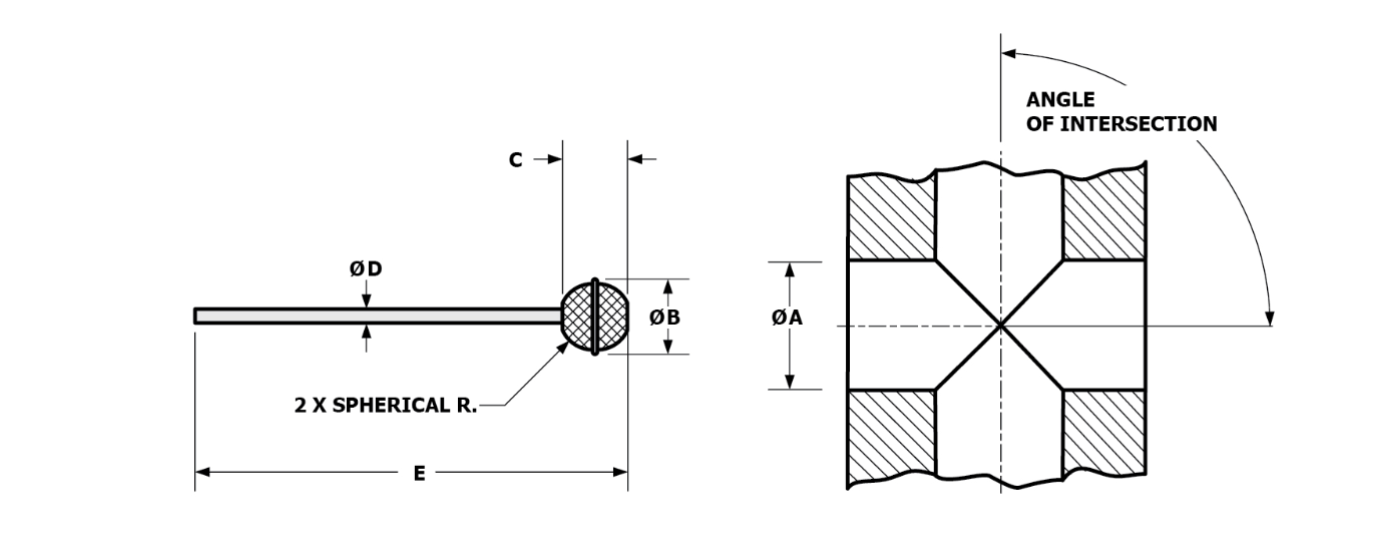
Available Configurations and Sizes
Available Configurations and Sizes
![]()
ORBITOOL comes in two configurations: one-hemisphere and two-hemisphere.
ORBITOOL Microtool 18000 Series
|
||||||||||||||||||||||||||||||||||||
One-Hemisphere Configuration Available Sizes
Please contact for specific application assistance.
|
|||||||||||||||||||||||||||||||||||||||||||||||||||||||||||||||||||||||||||
Single Hemisphere Cutter |
Reducing Sleeve (3.0mm or 1/8” O.D.) |
|
|
Two-Hemisphere Configuration Available Sizes
Please contact for specific application assistance.
|
|||||||||||||||||||||||||||||||||||||||||||||||||||||||||||||||||||||||||||
|
|
Available Configurations and Sizes (metric)
Available Configurations and Sizes
![]()
ORBITOOL comes in two configurations: one-hemisphere and two-hemisphere.
One-Hemisphere Configuration Available Sizes
ORBITOOL Microtool 18000 Series
|
||||||||||||||||||||||||||||||||||||
Please contact for specific application assistance.
|
|||||||||||||||||||||||||||||||||||||||||||||||||||||||||||||||||||||||||||
|
Reducing Sleeve (3.0mm or 1/8” O.D.)
|
|
|
Two-Hemisphere Configuration Available Sizes
Please contact for specific application assistance.
|
|||||||||||||||||||||||||||||||||||||||||||||||||||||||||||||||||||||||||||
|